Different way to generate GCode
Our specialized slicing software, Chisel, provides precise control over GCode paths and extrusion. While it does require more input compared to simply using a standard slicer with a closed mesh, its benefits are highly valuable:
- You can accurately adjust the width and height of extrusion lines, enabling non-planar print paths and variable-width walls.
- The software automatically generates efficient infill patterns based on outer wall contours.
- It features an advanced path-ordering algorithm that minimizes travel moves and retractions. Additionally, you have the option to manually override the automatic ordering with user-specified preferences.
Below are some comparisons between our slicer and standard FDM slicing solutions.
Sparse infill pattern
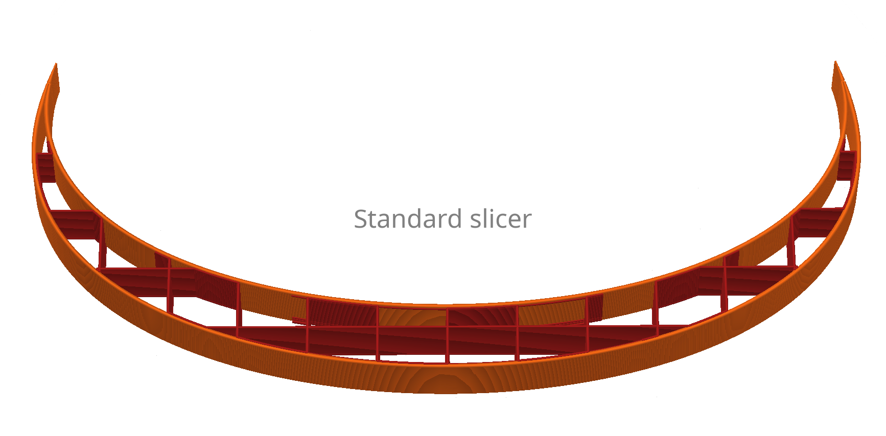
The image above illustrates a simple curved shape with a low-density (8%) grid infill, as generated by a standard slicer. In standard slicers, infill takes the form of a fixed geometric structure intersected by the perimeter loop.
While it is possible to alter the geometric pattern (such as grid, honeycomb, gyroid), adjust density, and change the base orientation (by rotating the model on the build plate), this infill structure consistently behaves like an isomorphic "foam" placed between perimeters, rather than oriented truss structures that closely follow the perimeter lines.
For structural applications, this approach poses a challenge. In instances with low infill densities, as seen in the example above, certain areas between perimeters can become excessively sparse, lacking efficient load transfer between object perimeters. While increasing infill density can resolve this issue, limitations in FDM technology, such as the minimal practical extrusion width, result in significantly heavier prints compared to dedicated structural foams. Furthermore, print times are considerably extended when higher infill densities are employed.
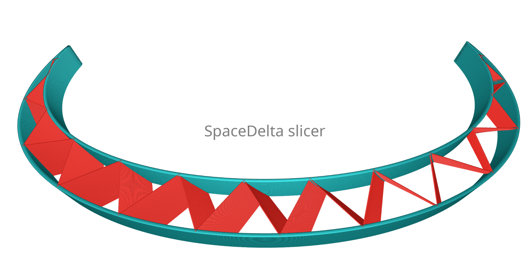
In our slicer, the infill is always associated with specific control perimeters, both upper and lower in the case of this C-shaped piece. This infill is typically executed as a single, continuous extrusion, creating an efficient truss structure (in this instance, a warren truss).
Considering the limitations of FDM technology, this approach tends to yield superior results compared to attempting to replicate an isomorphic "foam" structure. Even with a relatively thick minimal extrusion width (ranging from 0.3mm to 0.4mm), it establishes a lightweight yet dependable shear web between the load-bearing perimeters.
Within our slicer, you have the option to select from multiple infill patterns, each of which adheres to the designated control perimeters. Moreover, we employ various techniques, such as sine modulation in the z-axis, to enhance the efficiency of these infill patterns even further.
Full infill pattern
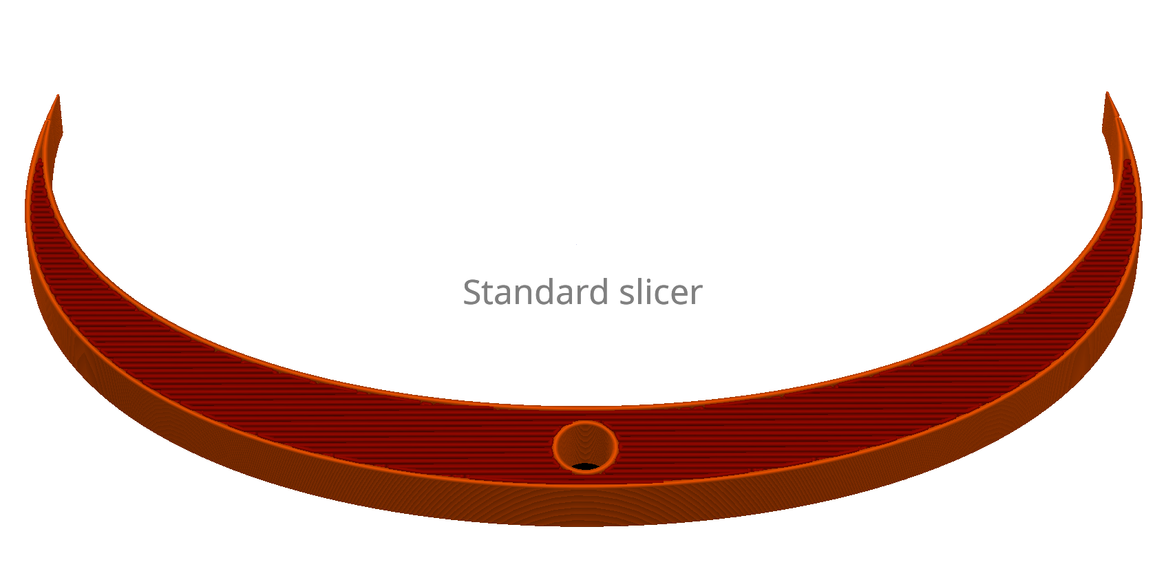
In this example, we've designated full infill for the section of the part where the infill intersects with a hole. As in the previous example, the full infill is executed as a static structure intersected by the perimeter loop, and in this instance, it comprises horizontal lines.
This type of infill necessitates numerous 180-degree turns by the toolhead, and occasionally, it involves crossing over previously printed full infill sections. This can heighten the risk of material accumulation on the nozzle and potential collisions, particularly with oozing filament materials like PETG.
Additionally, it's important to note that while all FDM filaments exhibit greater strength along the extrusion lines, filament compositions with glass fiber or carbon fiber additives show even more pronounced differences in this aspect. They often demonstrate 3-4 times greater stiffness and strength along the print direction. Therefore, it would be highly advantageous to align the extrusion lines with the perimeters, or make them perpendicular when prioritizing compression stiffness and strength. Achieving the first scenario (aligning the infill with perimeters) is feasible by employing multiple walls. However, the second scenario (ensuring infill lines are always perpendicular to the perimeters) becomes impossible in more complex cross-sectional geometries.
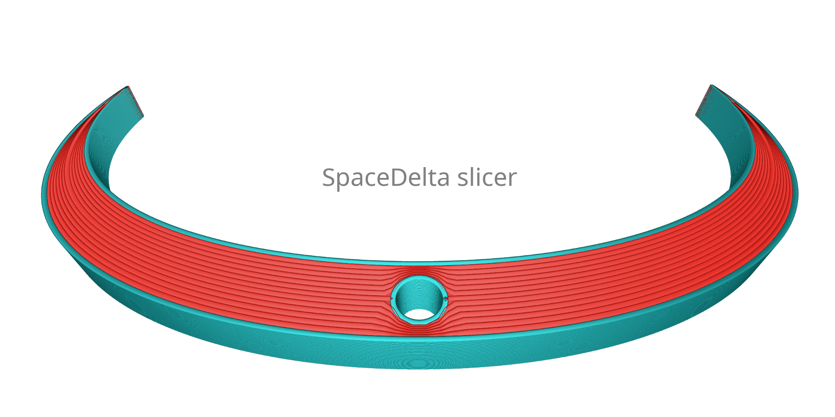
Just like the sparse infill types such as the warren truss, in our slicer, the full infill lines are guided by the control perimeters, leveraging variable extrusion width to completely occupy the space between them. This approach ensures efficient and robust infill for your prints.
Our slicer offers versatile options for infill line orientation between perimeters. You can choose parallel lines, perpendicular lines, or a combined type that alternates between parallel and perpendicular directions, providing flexibility to tailor the infill pattern to your specific needs.
Curved top section
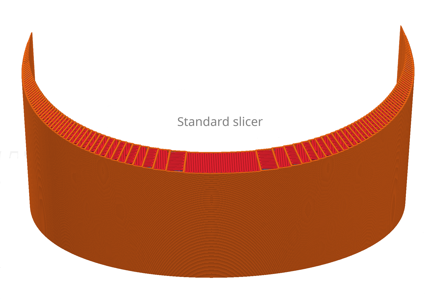
Standard slicers typically employ planar slicing, where each layer corresponds to a horizontal plane along the Z-axis. This approach can lead to noticeable stepping effects on slightly inclined surfaces, which become more pronounced with larger layer heights.
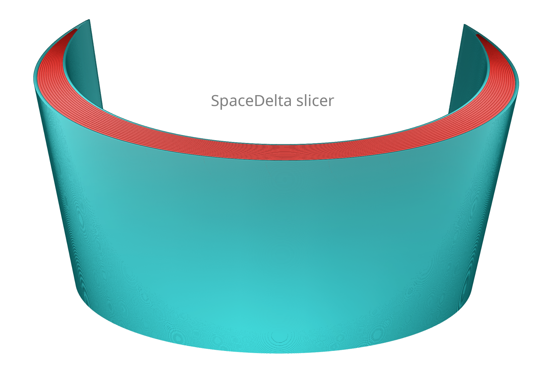
In contrast to standard slicers, our slicer is not confined to planar paths. It has the capability to generate true space curves for any perimeter line, allowing for the creation of smooth, step-less finishes on prints. This flexibility enables us to achieve superior surface quality and accuracy, especially on objects with complex and non-planar geometries.
The ability to create non-planar paths in our slicer not only improves surface finish but also enhances mechanical properties, especially when using GF/CF fiber-filled filaments.